
SX1278 is a low-IF transceiver with half-duplex transmission.
This device supports FSK GFSK MSK GMSK LoRaTM and OOK modulation methods. It mainly uses LoRaTM remote modems for ultra-long-distance spread-spectrum communications with strong anti-interference. The SX1278 supports a maximum link budget of 168dB, a constant + 20dBm / 100mW RF power output when the voltage changes, and a 14dB high-efficiency power amplifier, that is, the device can output + 20dBm or + 14dBm RF power at the same time. The device has a programmable bit rate of up to 300kps, high sensitivity down to -148dBm, and has an excellent anti-blocker. Compared with similar devices, the SX1278 significantly reduces the current consumption and significantly optimizes the performance of phase noise, selectivity, and receiver linearity.
Features
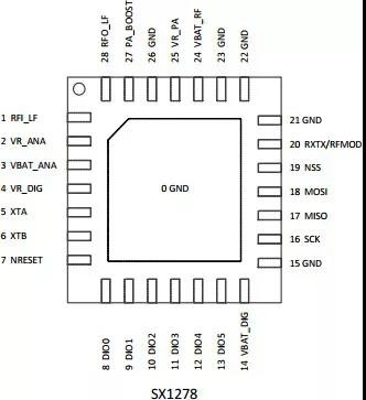
Pin Diagram
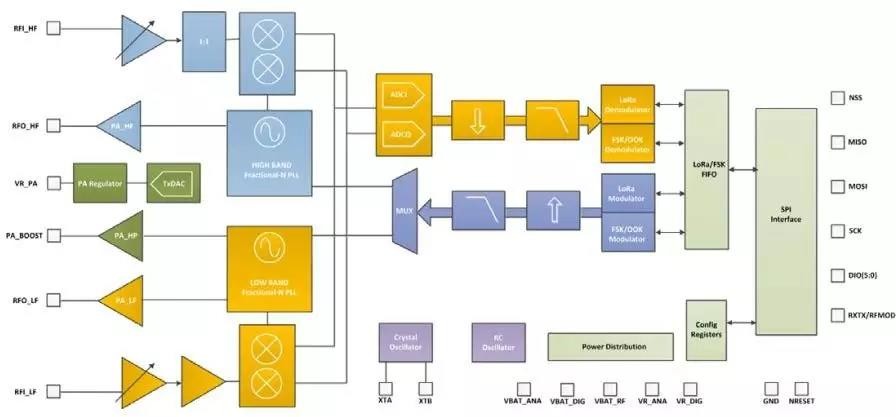
Block Diagram

Note: According to the data sheet of SX1278, it can be seen that the power from the 27th pin PA_BOOST pin can reach 20dBm during transmission, but the power consumption is low when transmitting, and the current is about 120mA. The RFO_HF pin comes out, the power can reach 14dBm, and the current can be as low as 29mA, which is suitable for application scenarios with low power consumption requirements. Here mainly introduces the hardware design scheme of low power consumption. The circuit is divided into two parts: the design of the schematic diagram and the design of the PCB.
Design of the schematic
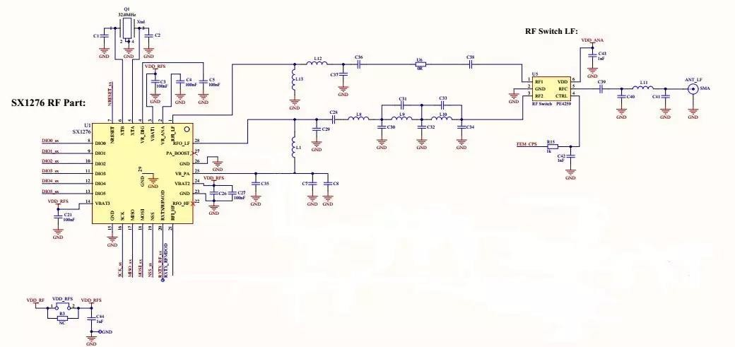
Overall framework: power circuit, reset clock circuit, radio frequency circuit and external interface circuit.
Power circuit

The 3rd pin VBAT1 (VBAT_ANA) of SX1278 is the power supply voltage of the analog circuit, the 14th pin VBAT3 (VBAT_DIG) is the power supply voltage of the digital part, and the 24-pin VBAT2 (VBAT_RF) is the power supply voltage of the RF circuit. The power supply circuit is mainly powered by these three pins. The power supply range is 1.8V-3.7V, and 3.3V power supply is recommended. The same power supply can be used. And at least one filter capacitor needs to be added at each power supply to reduce the ripple of the power supply to ensure the stability of the power supply.
Reset clock circuit

The crystal circuit has a passive crystal and an active crystal. Under normal circumstances, to ensure frequency accuracy and higher sensitivity, an active crystal is recommended. However, in order to ensure the smallest size, highest cost performance, and low cost, it is recommended to switch to a passive crystal. This not only saves costs, but also saves volume, but the receiving sensitivity performance of the module will definitely be lower, so the transmission distance will be slightly worse. The reset pin NRESET of this device is directly controlled by the IO port of an external microcontroller and is active low.
RF circuit
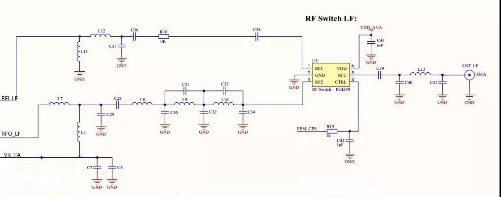
This device can be made separate for receiving and sending, but you need to add a radio frequency switch to select. This circuit recommends using a radio frequency switch PE4259 to control the sending and receiving and separate the receiving and transmitting branches. At the transmitting end, an elliptic filter is added to the matching circuit composed of inductors and capacitors, and then enter the RF switch. Pay attention to add DC blocking capacitors to prevent reception from affecting the transmission. At the same time, the receiving end is also an inductor and capacitor matching circuit. Straighten the capacitor to prevent the transmission from affecting the reception. A third-order π-type filter is added at the back of the RF switch, which helps to remove the second harmonic, third harmonic, and spurs of the transmission, and at the same time filters the received interference signal.
External interface circuit
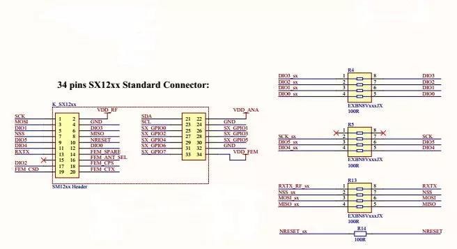
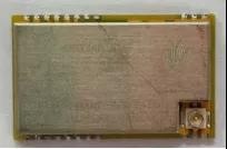
All the IO pins of SX1278 are led to the external interface, which is convenient for external microcontroller to control. For example, the E32-XXXT14S2 of Chengdu Yibaite Electronic Technology Co., Ltd. meets such requirements. It has added an external microcontroller to control the SX1278, and the package size is only 26 * 16MM. As a serial port module, it is also very convenient to use. It only requires users to operate. The serial port can be used for data transmission and reception control, as shown in the figure.
PCB design
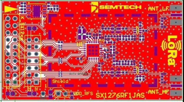
As shown in the figure, the layout is mainly the layout of the power supply and the layout of the radio frequency.
For power supplies, a filter capacitor must be provided next to each power supply, as close as possible to the power supply pins;
For radio frequency, it is better to keep the transmission path and the receiver away from each other to avoid mutual interference.
In terms of wiring, there should be no loop wires in the power wiring to avoid the formation of power loops. At least one ground via should be added to each filter capacitor. As far as possible, there should be no parallel lines in the RF wiring to avoid mutual inductance.