With the development of wireless data transmission,the application of wireless modules is becoming more and more extensive.Wireless modules are widely used in vehicle monitoring, remote control,telemetry, small wireless networks, wireless meter reading, access controlsystems, cell paging, industrial data acquisition systems, wireless tags,identification, contactless RF smart cards, small wireless data terminals,security and fire protection. System, wireless remote control system, biosignalacquisition, hydrometeorological monitoring, robot control, wireless 232 datacommunication, wireless 485/422 data communication, digital audio, digitalimage transmission and other fields.
The transmission distance of the wireless module is mainly affected by factorssuch as power, receiving sensitivity, and antenna. Mainly from these threeaspects to describe the method of increasing the transmission distance of thewireless module.
Transmit power
Emissive Power is the RF signal strength emitted by the wireless module. Intheory, the greater the RF signal strength, the farther the transmissiondistance is, that is, the high-power wireless module transmits farther than thelow-power wireless module.
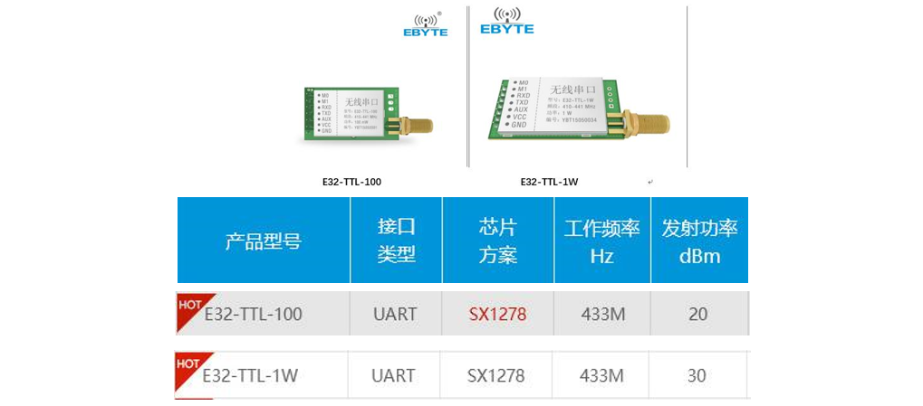
For example, compare the E32 series of Chengdu ebyte
Method for increasing transmission distance ofwireless module
Method for increasing transmission distance of wireless module, method forincreasing transmission distance of wireless module, method for increasingtransmission distance of wireless module
As shown in the figure, the frequency of both modules is 433MHz. The SX1278scheme and the UART interface transmit power are different, so the transmissiondistance is definitely different. From a theoretical comparison, theE32-TTL-100 has a small power and a closer transmission distance; theE32-TTL-1W has a larger power and a longer transmission distance.
2. Receive sensitivity
Receiver Sensitivity refers to the minimum signal level that a receiver candetect when a given receiver demodulator requires a signal-to-noise ratio. Thereceiving sensitivity of wireless transmission is similar to the hearing whenpeople communicate with each other. Improving the receiving sensitivity of thesignal enables the wireless product to have a stronger ability to capture weaksignals. Thus, as the transmission distance increases, the received signalbecomes weak, and high-sensitivity wireless products can still receive data,maintain a stable connection, and greatly increase the transmission distance.That is, the lower the receiving sensitivity, the farther the wireless moduletransmits the distance.
The formula for receiving sensitivity is as follows:
S=-174+NF+10lgB+10lgSNR
Where: NF is the noise figure, B is the signal bandwidth, and SNR is thedemodulation signal to noise ratio. The larger the bandwidth, the larger thenoise figure of the system, the greater the sensitivity and the worse thereception performance. This requires that the bandwidth of the system and theinfluence of the noise figure on the sensitivity should be considered whendesigning the receiver.
The receiving sensitivity of the wireless module is very important, especiallyin low-power transmission systems, each dB is important, especially the"6dB rule": increasing or decreasing 6dB means doubling or reducingpower by half. For example, when the transmitting energy of the transmittingend is 100mW or 20dBm, if the receiving sensitivity is -83dBm at 11Mbps, thetheoretical unobstructed viewing distance is 15km, and the receivingsensitivity is -77dBm, the theoretically transmitted unobstructed viewingdistance is only It is half of 15km (7.5km), or equivalent to a 1/4 reductionin energy at the transmitting end, which is equivalent to 25mW and 14dBm.Therefore, improving the receiving sensitivity of the receiving end in thewireless module transmission system is equivalent to increasing thetransmitting energy of the transmitting end and increasing the distancetransmitted by the wireless module.
3. Antenna
An antenna is a transducer that converts a guided wave propagating on atransmission line into an electromagnetic wave propagating in an unboundedmedium, or vice versa. Generally, the antennas are reversible, that is, thesame antenna can be used as both a transmitting antenna and a receiving antenna,and the same characteristic parameters of the same antenna as transmitting orreceiving are the same.
From the theoretical parameters of the antenna, the input impedance of theantenna and the gain of the antenna can determine the performance of the antennaand determine the transmission distance of the wireless module. From the inputimpedance of the antenna, the general antenna is made to a standard 50 ohms,and the impedance of the wireless module is also a standard 50 ohms, so thatthe antenna and the wireless module are completely matched to ensure that notransmission signal is lost, thereby ensuring the distance of the wirelessmodule. From the gain of the antenna, the total energy of the transmission isequal to the sum of the transmission power (dBm) and the antenna gain (dBi).The larger the antenna gain, the larger the total energy of the transmission,and the farther the transmission distance of the wireless module is.
From the actual test of the antenna, the actual environment at the scene cannotbe absolutely flat, such as hills, buildings, trees, and the degree and mannerof influence on the propagation of radio waves. Therefore, before theimplementation of the project, on-site radio wave propagation and receivingfield strength test (how many dBm is accurate) must be performed to determinethe power, antenna type, erection height and other parameters of the equipmentaccording to the site environment and work requirements, so that the uplink anddownlink signals are reached. Adequate anti-interference ability to achieveeffective and reliable wireless data transmission.
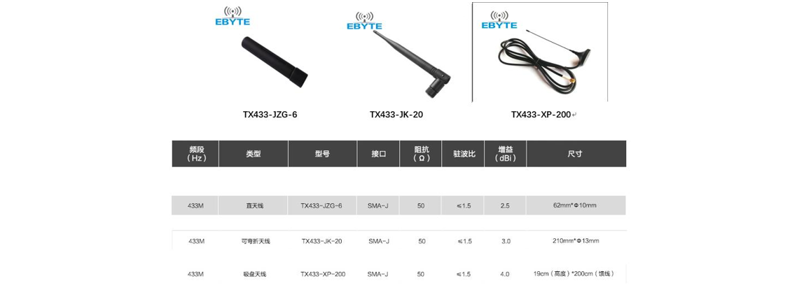
For example, compare the three 433M antennas of Chengdu ebyte
Method for increasing transmission distance ofwireless module
Method for increasing transmission distance of wireless module
As shown in the figure, the impedances of the three antennas are all standard50 ohms, and the VSWR is also less than or equal to 1.5. Only the gain isdifferent, so the transmission distance is definitely different. From thetheoretical comparison, the TX433-JZG-6 has the smallest gain and the closesttransmission distance, followed by TX433-JK-20. The TX433-XP-200 has thelargest gain and the longest transmission distance.
However, in actual tests, it is impossible to be absolutely flat and there isno obstruction, so the transmission distance of the wireless module is affectedby many factors, and there is no absoluteness.